Lab 4: Digital Audio
Introduction
In this lab the MCU was used to drive a small speaker to play short tunes. One of the basic timers on the MCU were used to generate the square wave for the speaker, and the other was used to handle generating the square wave for a certain duration. The design implimented played “Fur Elise” and the melody of “Blue(Da Ba Dee)”.
Design and Testing Methodology
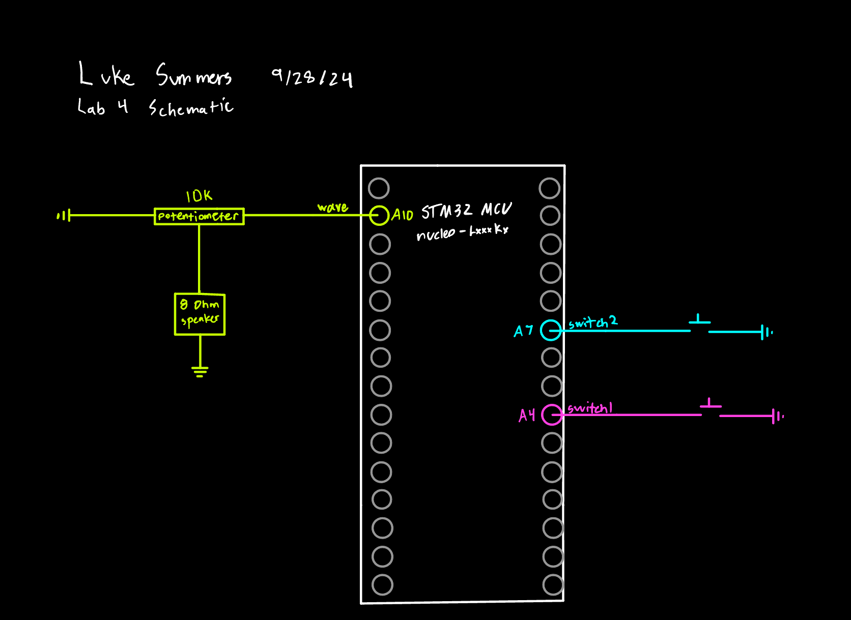
The square wave was generated using one of the basic timers on the MCU. With how the RCC clock configuration register was set, the clock that is fed into the timer was at a frequency of 1 Mhz. This was done by setting bits 4-7 of the RCC_CFGR register to ‘1001’. The prescaler on the clock was set to 1 as the input clock was already the desired frequency. In order to generate the square wave, the auto reload register of the timer was set so that counter overflow would happen at twice the desired frequency. The square wave was then made by clearing the timers status flag, writing one to the pin, waiting for one period of the clock to have counter overflow, reseting the timer status flag, writing 0 to the pin and waiting for another period of the timer, and then repeating. Since counter overflow will occur at twice the desired frequency, the output pin will have a wave that is at the desired frequency. The other basic timer was then used to output this square wave for the desired duration of time. The prescaler of this timer was set so that the clock frequency of the timer was 1 Khz. With a frequency of 1 KHz the counter of this timer would be incrementing once every millisecond, which means the auto reload register of the timer could be set to the desired number of milliseconds and then the counter overflowing could be used to trigger the stoppage of the square wave. In this way the two timers could be used to generate square waves at specific frequencies for a certain number of milliseconds which was used to drive the speaker. The design was tested by using the oscilliscope to measure the frequency of an output wave to compare it to the desired frequency of the design. The circuit included the MCU, a LM386 audio amplfier, a small speaker, and a potentiometer for volume control. It also used two switches to trigger the playing of each song.
The MCU has an onboard timer that is more robust that could have been used to generate a PWM signal that is connected directly to a pin. In creating the design for this lab, generating a square wave with this method was tested and I found it to be about as accurate as the method I used with two basic timers, so I chose the simplicity of using the basic timer.
Technical Documentation:
The sourcecode for the project can be found in the Github repository.
Schematic

Figure 1 shows the circuit for the design.
Calculations

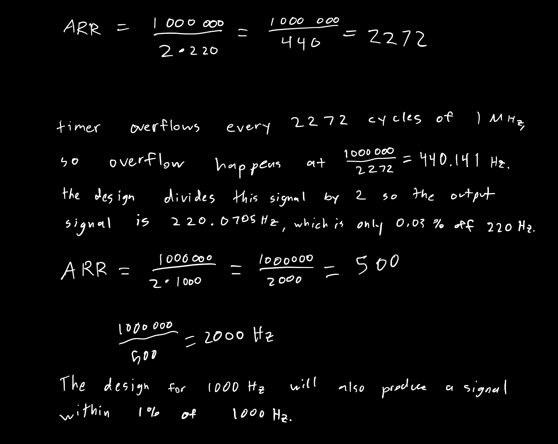
Figure 2 shows the calculations done for the accuracy of the design at outputing a wave in the range of 220 Hz to 1000 Hz. Since the design is within the standard for 220 Hz and 1000 Hz, it will be within the standard for all frequencies in between.

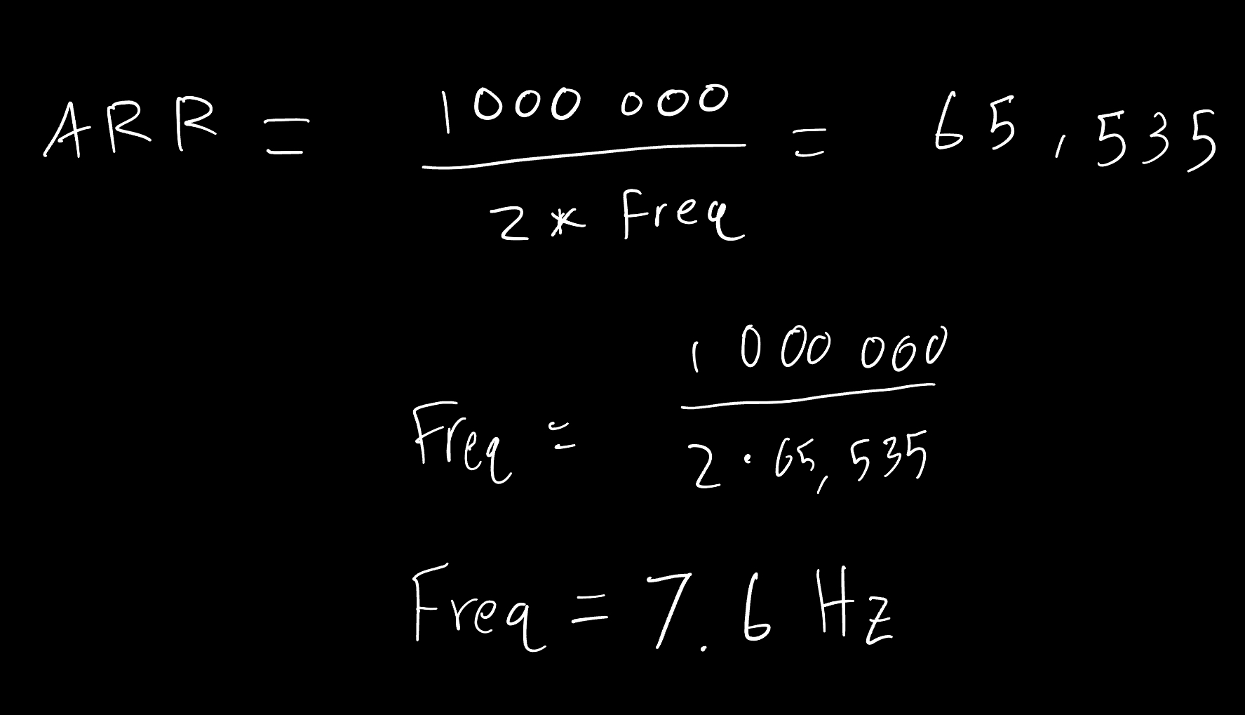
Figure 3 shows the calculations done for the frequency and duration ranges. The minimum duration is 0 ms and the maximum is just the maximum that the ARR can be set to, which is 65,535 because the ARR has 16 accessible bits. Thus the maximum duration supported is 65.545 seconds. The design could be changed to increase this value by changing the clock frequency of the timer. The design supports a freqency of 0, but that just outputs nothing. The minimum frequency it can generate is 7.6 Hz, as the ARR can be set to 65,535 which would produce counter overflow at 15.2 Hz. The output frequency would then be 7.6 Hz. The maximum is just the timer clock frequency which is 1 Mhz. The timer clock frequency could be changed to achieve frequencies outside of this range if desired.
Results and Discussion
Oscilliscope Reading
Figure 5 shows an oscilliscope reading of the output pin when trying to output a 220 Hz signal. The ARR was set to 2272 so that counter overflow would occur at twice the desired frequency, as the design would toggle the pin at half of the frequency of counter overflow. Due to the system not being to function instantaneously the output signal was a little slower than desired but within the requirements.
Figure 5 shows an oscilliscope reading of the output pin when trying to output a 1000 Hz signal. The ARR was set to 500 so that counter overflow would occur at twice the desired frequency, as the design would toggle the pin at half of the frequency of counter overflow.
Example of Design
The video above shows the design playing both of the desired songs, along with the potentiometer being used to control the volume.
Conclusion
The MCU’s on board timers were used to generate certain frequencies of square waves for certain durations in order to drive a small speaker. I spent a total of 10 hours on this lab.