Lab 6: The Internet of Things and Serial Peripheral Interface
Introduction
In this lab the MCU was used to interface with a DS1722 temperature chip to read temperatures and then sent the temperature reading to an ESP8266 chip that hosted a webpage that showed the temperature. Upon a request on the web server, the MCU would interface with the DS1722 via SPI, convert the SPI values into a temperature, and then send the updated webpage to the ESP8266 via UART. The web server could also be used to control an LED on the developement board. The SPI transactions were debugged using a logic analyzer on an oscilliscope.
Design
The STM32L432KCUx MCU has onboard peripherals that can enact SPI and UART. The onboard USART peripheral was used to communicate the webpage to the ESP8266. In the loop of code that the MCU continuously ran, the MCU would first wait for a server request to come in over UART. The MCU would then enact an SPI transaction with the temperature chip to get the most recently stored temperature and convert the CIPO register values into a single float of the temperature. The loop would also update the status of the LED upon the request. The MCU would then send the updated wep page back to the ESP8266 via UART. The ESP8266 created a wifi network and displayed the network on a network private IP address.
The DS1722 supports 8, 9, 10, 11, and 12 bit resolution values for reading the temperature. The web page had buttons to contorl the resolution of the temperature readings taking place. The chip had two 8 bit registers to store the temperature reading value. The first register contained the 8 bits of the temperature that were the whole number value of the temperature, stored in the register as an 8 bit two’s compliment value. The second register was used to store the fractional portions of the temperature reading if the resolution was above 8 bits. The DS1722 supported continuous and ‘one shot’ temperature reading modes, where in continuous mode the temperature registers were continually updated with the most recent temperature reading and in one shot mode the registers would be updated with a temperature reading when prompted by interfacing with the chip’s configuration register. The design used the continuous reading mode. Due to the temperature reading taking some amount of time depending on the resolution, there was a bit of latency between updating the resolution and when the temperature reading would be in that resolution. The configuration register was also used to control the resoultion of the temperature readings takng place.
Technical Documentation:
The sourcecode for the project can be found in the Github repository.
Schematic

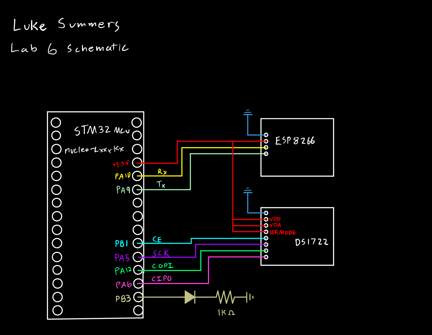
Figure 1 shows the circuit for the design.
SPI Configuration
The MCU was configured as the controller for the SPI transactions with the temperature chip as the peripheral. The CE signal was controlled manually in software. The data size for the transactions was 8 bits. The peripheral divided the input clock signal by 256. The phase was set so that data capture occurred on the second clock transition. The temperature chip supported both types of clock polarity, and an idle low clock polarity was used.
Results and Discussion
The design was successful at interfacing with the temperature chip to make temperature readings, control the LED, and send the information to an internet accessable webpage. The web page was successful in controlling the LED and the resolution of the temperature readings taking place. Due to the time required to calculate a temperature reading, whenever the status would change it would take multiple refreshes for this to be reflected in the temperature. More complex web developement techniques could have been used to make this process smoother, but that was out of the scope of the lab. A can of compressed air turned upside down was used to create negative temperature values on the chip, and the design was successful in handling these negative temperatures.
Example SPI Transaction

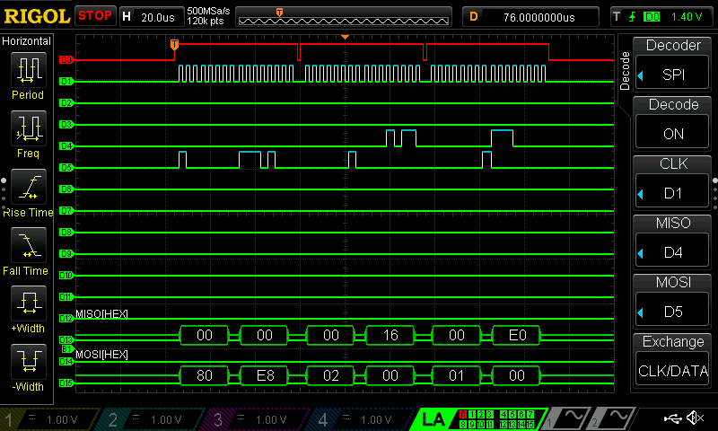
Figure 2 shows an example SPI transaction read on the logic analyzer. The first two transactions configure the chip to make a 12 bit temperature reading. The second two read the whole number temperature value register. The last two read the fraction temperature value register.
Conclusion
The MCU succesfully interfaced with the two peripheral chips using UART and SPI to create a webpage to control and show the LED and temperature status. I spent around 30 hours on this lab, but this was massively inflated by my shortsightedness about the unreliability of the logic analyzer head and wiring my output to pin 6 on the FPGA as apposed to the desired pin A6 on the MCU.